Jump to content

Welcome to Geeks to Go - Register now for FREE

Need help with your computer or device? Want to learn new tech skills? You're in the right place!
Geeks to Go is a friendly community of tech experts who can solve any problem you have. Just create a free account and post your question. Our volunteers will reply quickly and guide you through the steps. Don't let tech troubles stop you. Join Geeks to Go now and get the support you need!

How it Works Create Account
Photo

Mobo front panel connections


  • Please log in to reply

#1
syco123

syco123

    New Member

  • Member
  • Pip
  • 9 posts
Hi
This is my first mobo change. Im fitting a HP vectra Micro ATX, PIII 370 motherboard. It's all going OK so far, only problem is I've looked through all the manuals online but cannot find the details on how to fit the front panel connections. I'm a little wary about trial and error. If I can't find the information I need, and it's looking like I can't, what are my chances of destroying my replacement mobo??

If anyone has a HP vectra Micro ATX, PIII 370 fitted and have have a quick look at, at least, the power switch, I'd really appreciate it.

mobo pic attached

Thanks

Attached Thumbnails

  • mobo.jpg

  • 0

Advertisements


#2
BlackPandemic

BlackPandemic

    Member

  • Member
  • PipPipPip
  • 678 posts
Trial and error isn't usually a bad idea. At one point, I was fooling around to find a way to turn off the front LED's on my computer (because I'm going to college and this thing lit up my basement...just imagine a dorm room). First thing, remember the configuration things were in before starting trial and error. Second, if something doesn't work...then...it doesn't work. Fooling with whatever connects to the front shouldn't fry your mobo.
  • 0

#3
syco123

syco123

    New Member

  • Topic Starter
  • Member
  • Pip
  • 9 posts
Thanks for the reply BlackPandemic

I've not got anything connected yet, the confirguration is completely different from the old mobo. Also should have said there no markings on the board.

I'll wait a little wile just see if anyone with a similar mobo posts then i'll give it a go then and hope I dont hear any sizzling :whistling:
  • 0

#4
BlackPandemic

BlackPandemic

    Member

  • Member
  • PipPipPip
  • 678 posts
So the mobo you just bought didn't come with a manual? Is this retail or OEM? Also, what are the front panel connectors...like...what are they? USB, Firewire, audio, etc.
  • 0

#5
Jack123

Jack123

    Trusted Tech

  • Retired Staff
  • 944 posts
01-syco123 [Motherboard Front Panel Connection]
11th June 2006

syco123 – Welcome to – Geeks to GO –

Need to know more info on your PC – Apparently this Motherboard – is used by Dell – Compaq and probably by HP – It looks as if each model of this card might have small – but significant configuration differences – depending on basic PC model that it is being used on.

You cannot use – Trial & Error Method – with these Proprietary Manufacturers – They use different Power Wiring Standards – So it is – Very important to know which Standard – you have –

Wiring to the wrong Standard can be fatal to the Motherboard & You –

So give more details on –
(1)- What is being Replaced
(2)- Why it is being Replaced
(3)- Power Supply installed – Make & Model – To verify Compatibility –
(4)- Make & Model of PC & Type-Desktop – Tower –
(5)- Need to verify – Compatibility with Manufacturer –

Here is the resultant link - Google Search Result – HP vectra Micro ATX, PIII 370 – Power Switch Wiring – It is a starting point – but need more info on the PC configuration -

http://h10061.www1.h...374479&search=0

Jack123

Edited by Jack123, 11 June 2006 - 11:44 AM.

  • 0

#6
SRX660

SRX660

    motto - Just get-er-done

  • Technician
  • 4,345 posts
I have a vectra. There is no front usb connectors on the vectra motherboard. The only way to get front usb is with a PCI card.

The power switch wires are this( going by your numbering system.
1. white 2. red 3. green 4. no wire 5. yellow 6. white 7. blue 8. white 9. orange 10. white

Someone has already done what you are doing. It is an interesting read.

http://www.geekstogo...44&hl=superstar

I explained there what each wire was for.

SRX660
  • 0

#7
syco123

syco123

    New Member

  • Topic Starter
  • Member
  • Pip
  • 9 posts
Front USB is not required. The only connections are the power-on switch, the reset, the HDD access LED and the power LED.

This PC was bought working, second hand and died 2 days later during a debian linux install. No reason for the failure as far as I could tell. Bad luck i think!

Old board
Intel Server Board S815EBM1

Another forum thought the Vectra VL400 would be an OK replacement. Bought off Ebay from a computer parts reclaimer with a good and high positive rating. No manual just online PDF's

The board is being replaced due to what was most likey a IDE controller failer on the server board (a decision come to from help on another forum). I decided to find another board and not add a PCI IDE controller card as the old board doesnt have an AGP slot and I have a 128Mb graphics card that I'd like to fit. My rationalle being, if i have to buy bits i might as well buy bits that allow me to upgrade.

power supply is a Vastec VT-235 ATX

The PC is a desktop with no markings on the case and came from a home office where it had been used as a linux server for a couple of years and was sold due to server upgrade. Possibly home built from scratch?

Ive got 256Mb and 128Mb of ram an 80Gb ATA HDD, floppy and CDR.

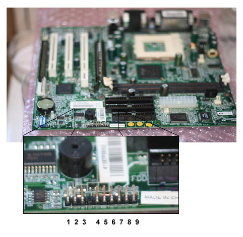
I have small connections for each switch/led each with 2 wires and this is different form the HP case connection which connects all the pins in a single plastic block. If you're fitting to a compatible HP case then you dont need to know which wire is for what, you just connect them all at the same time. Because of this there isn't any referance to what pic is what (I've read all the info I can find on the HP site) only referance to the 'front panel switchs' and in rebuild info, it just says to connect them. If its a straight board swap then its no problem, but this ins't a swap so I have no idea where to go.

SRX660

The wires from the connections on my case are not likeky to be colour coded the same as the PC in the other thread. Is it possible you can put the pin numbers in my pic to correspond to this list?

Power on
reset
HDD access LED
Power on LED

Being switchs it shouldnt matter if they are put on the right pins but the wrong way round, same with the LEDs it just means the LEDs wont work and the connection can just be reversed. If I know the pin pairs then I can try it out.

As for the rest of the compatibility issues It would be nice to know if the board is compatible with at least the power. So any help with that would be good.

Edited by syco123, 11 June 2006 - 12:46 PM.

  • 0

#8
syco123

syco123

    New Member

  • Topic Starter
  • Member
  • Pip
  • 9 posts
SRX660

found the info in your other post, thanks! Will hook up the switches and let you know how it goes.
  • 0

#9
syco123

syco123

    New Member

  • Topic Starter
  • Member
  • Pip
  • 9 posts
Just tried and It wont even boot.

When i hit the power on the monitor screen flashes momentarily the processor fan comes on (and the PSU fan). The onboard network connecton orange LED comes on with the PSU being powered up. Nothing else. couple of clicks from maybe the network connecting and possibly the HDD but who can tell that.

When I release my finger from the power on switch the power on LED goes out. If I try t turn it on again and hold my finger on the power on switch the LED stay on but the system doesnt just beep it plays a tune! seriously, I've never heard anything like it before.

In the other thread Samm talks about the PSU motherboard fan connection and superstar says he used a jumper to over come the problem. It doesn't boot at all so doesnt get as far as loading windows so I don't think i even got to that problem yet, lol. COuld it cause it not to boot at all?

Would appreciate any help any of you can give at this time. I've been at this for 2 weeks and am feeling pretty low about my first mobo replacement. Is it time to give neg feedback for selling a dodgy mobo, is it simply not compatible at all or do I still have things I can try here?

Edited by syco123, 11 June 2006 - 01:37 PM.

  • 0

#10
SRX660

SRX660

    motto - Just get-er-done

  • Technician
  • 4,345 posts
Yes, if you do not use a jumper for the PS fan, the computer will not boot up at all.The "ON" switch is a momentary switch. All it does is tell the motherboard that it has power. the motherboard turns on and goes thru the bios to see everything else. Holding the switch in just tells the motherboard you want to shut the computer off. Even with a bad hard drive( no OS)you should be able to boot to a blinking curser in the top left corner, if the hardware you need to boot is hooked up. I boot motherboards on a pizza box with just MB-CPU&fan-1 stick of memory-video( either onboard or a card)- and hard drive. a power supply is placed next to the MB and hooked up. PS mouse and keyboard also. no cdrom drives are hooked up. I usually will try booting to the bios to see whats there( rapidly htting the delete key while the computer is starting). I've been building puters for a few years so i have a lot of spare parts laying around. I might try swaping a few parts but if i soon don't get to the bios i throw the board away. I get these old puters all the time as trade-ins. I have 5 vectras in parts laying around. I give the people $50 off the computer price for the tradein as i really don't have much use for them. Some i give away to kids i think could use them.

Don't give up yet as this is a good learning experience for you. Soon you will be upgrading and fixing your own computers so you don't have to spend the $40-50 per hour shops charge. You will soon become very intimate with the newegg website just for the information there. You've been geeked.

SRX660
  • 0

Advertisements


#11
syco123

syco123

    New Member

  • Topic Starter
  • Member
  • Pip
  • 9 posts
so looking at the pic in the other thread I added the jumper to the two pins the correspond to the green wire on the middle and the black one below it (taking 'below' as the bottom of the picture). Can you confirm this is correct?

But still no boot. The CDR has power now though.

Tell you what im learning is how to get frustrated. Thanks for your help up to now though.

Any ideas what I can do next?
  • 0

#12
SRX660

SRX660

    motto - Just get-er-done

  • Technician
  • 4,345 posts
The next thing to try is to install a video card and try booting with the monitor connected to the card. It may be the onboard video is not working. This may not work also since the usual thing to do is disable the onboard video so the computer looks to the video card, but you cant do that if you cant get any video at all. It still might work, tho. I wonder if the cmos battery on the MB is dead so the computer cant read the bios when starting up. You might try replacing it. Having power to the cdrom drive says the MB is getting power.

You will have to experment with the jumper for the psu. It may be the other wire that needs to be jumpered. Switching the jumper between trying to boot the puter should not hurt the Mb. It should just not boot.

After building computers for a while you learn to not get frustrated at them. I think of it as being fun expermenting until i can get a computer up and running. There always seems to be some little trick i can try to get them to work. I had a computer that would not boot to a XP cd no matter what i tried. I finally downloaded the exe file from microsoft that makes the 6 floppy set of boot disks. After having to make a second set of disks because of a bad 3 disk in the first set, i finally was able to load XP to the HD of the computer. Frustrating? Yes, it was at the time, but i learned something from it. I never give up too easily. Theres always another trick i have learned to try. Its always been fun for me.

SRX660
  • 0

#13
HaraldR

HaraldR

    Member

  • Member
  • PipPipPip
  • 193 posts
Found this at HP hope it is of use:
HP Vectra or e-PC - How is the Status Panel Connector Wired

Pin Signal

1 Power Led green standby
2 Ground
3 Power Led Green on
4 Key Lock sw
5 VCC Power
6 Ground
7 Power button return path
8 Ground
9 Lock Led Amber

As near as I can figure pin 5 and 7 should be Pwr sw
But also Keylock pin 4 may need to got to 5 as well to allow power on(old security key disable feature)
leds should all be to ground to work

Manual

Pin Layout
  • 0

#14
syco123

syco123

    New Member

  • Topic Starter
  • Member
  • Pip
  • 9 posts
thanks HaraldR I think i've got the power switch connected, the problems persist though.

Unable to fit the video card as it's in a box in storage abot 3000 miles away! One of the reasons I didn't mind buying this with a server board in the first place. PC im using now has onboard video only. So I'm a bit buggered on that.

I am learning a [bleep] of a lot trying to fix this, but i don't see a result coming, unless I throw money I don't have at it. Certinly not frustrated with anyone trying to help me :whistling:

I've replaced the bios battery and I've tried the jumper in both positions but still nothing.
  • 0

#15
SRX660

SRX660

    motto - Just get-er-done

  • Technician
  • 4,345 posts
Syco123, it is now time for you to contact the Ebay person you bought the Mb from and tell them what you have tried doing to get it going. See if they will replace the board with one that works. coulda, woulda, shoulda just doesnt cut it when buying from Ebay. I would not take any excuses from them. You may end up buying a bad MB(if they refuse to guarantee the item) by buying from Ebay. I have bought a few items that were bad once in a great while. Mostly i have had not had problems when buying from Ebay buy there are exceptions always. See what the vendor can do for you.

SRX660
  • 0


Similar Topics

1 user(s) are reading this topic

0 members, 1 guests, 0 anonymous users

As Featured On:

Microsoft Yahoo BBC MSN PC Magazine Washington Post HP